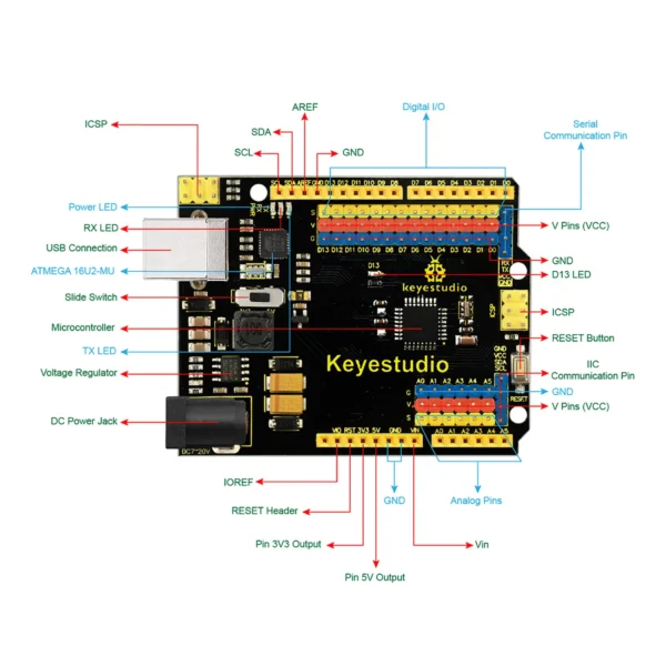
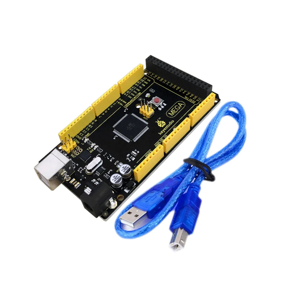
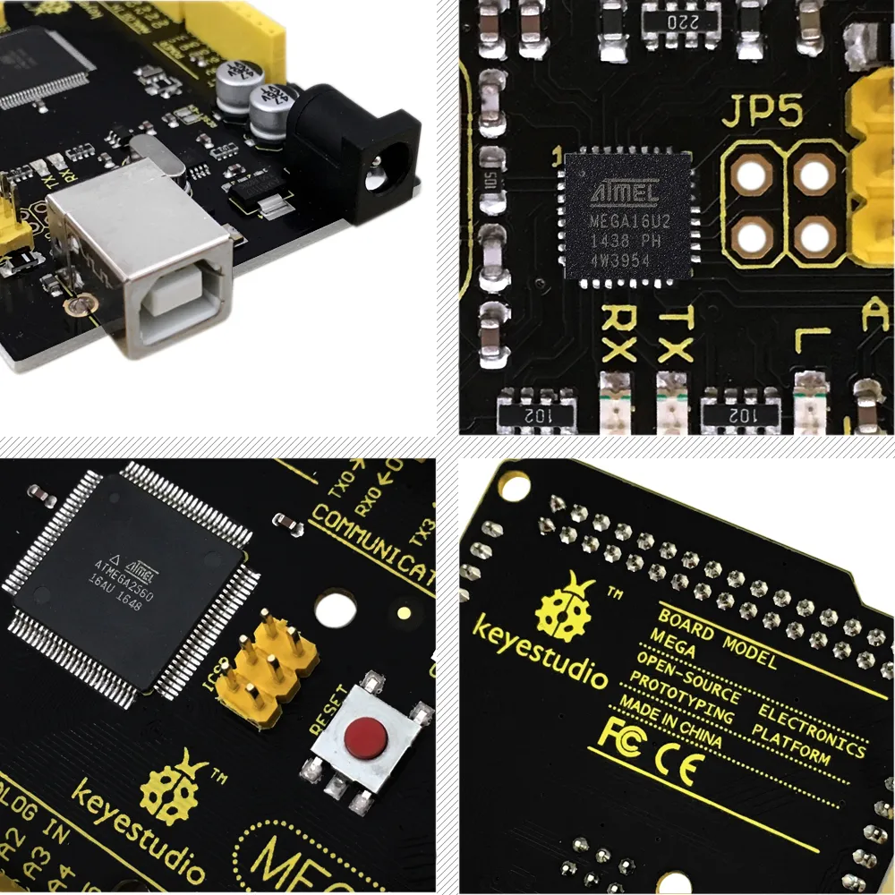
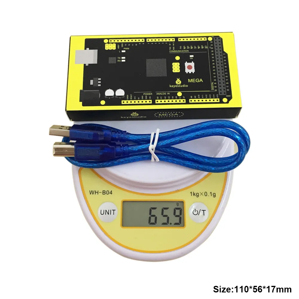
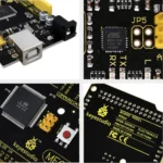
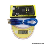
It has 54 digital input/output pins (of which 15 can be used as PWM outputs), 16 analog inputs, 4 UARTs (hardware serial ports), a 16 MHz crystal oscillator, a USB connection, a power jack, 2 ICSP headers, and a reset button.
It contains everything needed to support the microcontroller. With its bootloader, program can be downloaded directly with USB and you don’t need to use other external programmer.
Just simply connect it to a computer with a USB cable or power it with a AC-to-DC adapter or battery to get started.
The Mega 2560 board is compatible with most shields designed for the Uno.
The 2560 R3 differs from all preceding boards in that it does not use the FTDI USB-to-serial driver chip. Instead, it features the Atmega16U2 programmed as a USB-to-serial converter.
The MEGA 2560 is designed for more complex projects. With 54 digital I/O pins, 16 analog inputs and a larger space for your sketch, it is the recommended board for 3D printers and robotics projects. This gives your projects plenty of room and opportunities.
Microcontroller:ATMEGA2560-16AU
Operating Voltage:5V
Input Voltage (recommended):7-12V
Digital I/O Pins:54 (D0-D53)
PWM Digital I/O Pins:15 (D2-D13; D44-D46)
Analog Input Pins:16 (A0-A15)
DC Current per I/O Pin:20 mA
DC Current for 3.3V Pin:50 mA
Flash Memory:256 KB of which 8 KB used by bootloader
SRAM:8 KB
EEPROM:4 KB
Clock Speed:16 MHz
LED_BUILTIN:D13


